Name:_________________________________________________Date:_________
Circuit Construction Kit
Website: http://phet.colorado.edu/ → Go to "Play with Sims" → Go to "Physics" → Go to "Electricity" → Click on Circuit Construction Kit (DC Only), Virtual Lab → Click "Run Now" to start the simulation
Part I: Simple Circuits
I. Simple Circuit - Create a simple circuit that has one battery and 3-8 wires. As you change parts of your circuit record the outcome using this simple KEY when compared to this single simple circuit.
BB = bulb brighter | BD = bulb dimmer | F = fire | X = did not work | N = no change
1. Add another light bulb __________
2. Add another battery _________
3. Add 5 batteries _____________
4. Make the voltage of a battery smaller (right click on battery) ____
5. Place the lightbulb closer to the battery _______
6. Add more wire (try creating a very long circuit) _____
7. Place a bulb between two batteries ____
8. Place two batteries next to each other (single bulb) ____
9. Increase the voltage of a single battery to the maximum ____
10. Attach only one wire to the bulb ____
II. Grab Bag - Open the bag in the top right corner and test the materials in the bag to determine which are conductors. Rank them according to this scale
0 = not a conductor | 1 = slight conductor | 2 = good conductor | 3 = Great conductor
Dollar Bill _____ Paperclip ____ Penny ____ Eraser ____
Pencil Lead ____ Hand ____ Dog ____
III. Switches - Switches can be used to turn on and off lights, but a switch simply functions by breaking a circuit. Create a circuit with two lightbulbs, a battery and a switch.
Sketch your set-up:
What happens to the lightbulbs when you turn the switch on and off?
IV. Resistors - Set up a circuit with 1 battery, and 1 bulb. Add a resistor.
What happens to the light bulb when you add a resistor?
VI. Positive and Negative - Set up a circuit with two batteries.
Flip the battery around and reconnect the circuit. What happens?
Add a third battery? Does the light work now? Explain why you think this happens.
PART II: Advanced Circuits
I. Measuring Voltage
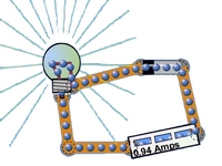
 Click the "Show Values" button and add a Voltmeter to the board. Set up a circuit that has one battery and one bulb as shown in the image.
1. What happens when you switch the black and the red wires? ___________________
2. What happens when the voltmeter wires are on the same side of the battery? ____________
3. Place another battery in the circuit next to the first battery. Now what is the voltage? _______
II. Using Schematics
Schematics are used by electricians to diagram circuits as they would be connected in houses, large buildings or even small electronics. Click on the "Schematic button" to see what each symbol means.
4. Draw the symbols for:
RESISTOR and BATTERY and SWITCH
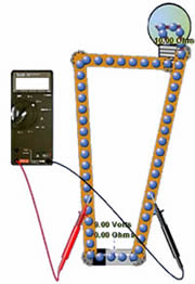
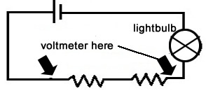
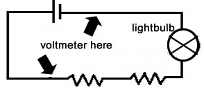
5. Set up the following circuit and test the voltage by placing the voltmeter in the locations shown. List the voltage for each of the locations.
Voltage = _______________ |
Voltage = _______________ |
Voltage = _______________ |
Voltage = _______________ |
III. Series Circuits
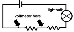
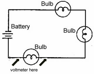 6. Set up the circuit shown on the schematic.
Use the voltmeter to determine how much voltage is going through each bulb. To do this make sure the wires of the voltmeter are positioned on either side of a single bulb as shown by the arrows on the diagram.
How much voltage is going through a single bulb? __________
7. Remove a bulb.
Now how much voltage is going through a single bulb? _______
8. The battery is 9 volts. Based on your observations above, how many volts would pass through a bulb if there were 9 bulbs on this circuit? _________
9. Place a switch directly after the battery. What happens when you turn the switch on or off?
IV. Parallel Circuits
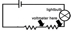
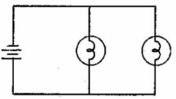 1. Set up the circuit as shown by the schematic.
How much voltage is going through each of the bulbs in the circuit? ________
2. Add a third bulb.
How much voltage is going through each of the bulbs now? ________
3. Based on your observations, is it better to wire a house using parallel circuits or series circuits? _____________________
4. The diagram below shows two lights (parallel circuit) with two separate switches. Set this up on the simulator.
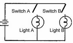
What will happen if you turn switch A on?
a. light A turns on b. light B turns on c. both lights turn on
